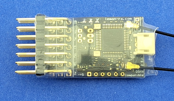
MR001c Bottom
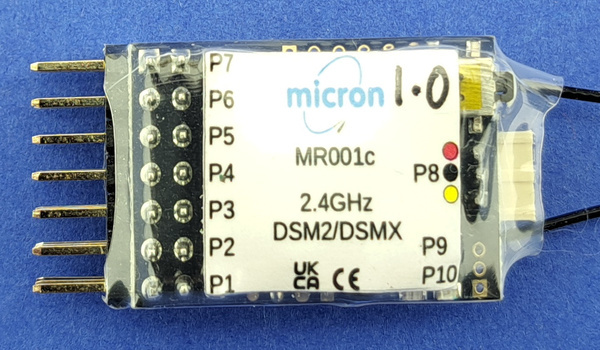
MR001c Top
The MR001c receiver is well suited for use in large
scale live-steam or large scale battery powered locos.
It operates on 2.4GHz using the Spektrum DSM2 or DSMX protocols;
thus it operates just like any other DSM2/DSMX receiver but includes some useful
features for model railway control.
The MR001c is small (30x18x11mm) and space for it is easily found in most locos.
The MR001c free-air range, when used with a Micron low-power transmitter,
is 50m-60m and approximately 200m when used with
a full-power (100mW) transmitter.
This range will be reduced indoors due to absorption by furniture / fittings
and reflections from metal surfaces.
Range is also reduced if the receiver aerial is in a metal enclosure.
Ideally, the aerial should be placed outside the vehicle body and clear of
any metal.
The active tip of the extended aerial needs to 'see' the transmitter so
should be placed through a hole in the vehicle body - e.g. into the cab space.
The receiver aerial should not be cut short or made longer as this will
affect operation of the receiver.
It is important to perform a range check after installation to ensure
you have full control of your loco/vehicle at all positions around the layout.
Features (top)
- Compatible with all DSM2 and DSMX transmitters with up
to 10 R/C channels, both Micron
model rail and aero model stick type transmitters.
- 3.45V to 8V working voltage range.
- 10 outputs which can be configured for servo/ESC or 0V/3.3V
low-current switched ports; 7 ports are at the front with 'standard' 0.1"
pitch connector pins, port 8 is on a JST-ZH connector at the rear
amd ports 9 & 10 are on an optional Molex Picoblade connector at the rear.
- Supports the Selecta feature
for compatibility with multi-loco transmitters, the receiver must
be re-bound to change Selecta switch position.
- The default configuration provides auto-switched front and rear
LED lights on P6 and P7 controlled by the throttle channel.
- Receiver on-board LED can be repeated to any non-servo output (this is
called the LED2 function).
- All functionality may be configured by programming using a
a suitable transmitter (most Micron tx or a stick type
model aircraft tx).
Connections and Indicators
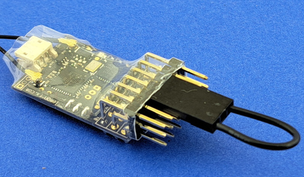
MR001c has 7 set of JR style 0.1" pitch output pins,
labeled P1 to P7 on the diagram below.
Ports P8 to P10 are on the JST-ZH and Molex Picoblade connectors at the
aerial end of the receiver.
Although the JST-ZH socket has 3.3V power, this is insufficient for powering
a servo which must use an external regulator or by power directly from the battery.
MR001c can be powered from a battery of 3.45V up to 8V;
use of a 4 or 5 cell NiMH rechargeable battery or
the 5V regulated output from a speed controller is typical.
MR001c contains 4 configurations
which can be selected using a
Power-On Configuration Changes or
by programming the receiver.
The default configuration has servo outputs on P1 to P5,
front/rear lighting on P6 and P7, a R/C channel 5 switched output
on P8 and R/C channel 3 switched outputs on P9 and P10:
| P1: | servo on ch1, throttle |
| P2: | servo on ch2, F1 on Tx20, optional servo on ch7
for Selecta transmitters |
| P3: | servo on ch3, toggle switch on Micron tx |
| P4: | servo on ch4, F2 on Tx20 |
| P5: | servo on ch5, bind button on Micron tx |
| P6: | front LED & LED2 |
| P7: | rear LED |
| P8: | idle 0V, 3.3V when ch5 is low (Micron tx bind button) |
| P9: | idle 0V, 3.3V when ch3 is low (Micron tx toggle down) |
| P10: | idle 0V, 3.3V when ch3 is high (Micron tx toggle up) |
Other output configurations are available on request.
The P8 JST-ZH connector also has 3.3V and 0V pins as
shown in the diagram below.
Connectors with 100m leads are optionally available for the P8 and P9/P10 sockets.
MR001c has 2 LED indicators, one on the top near the aerial and another
on the bottom, these are labeled 'LED RF' and 'LED CPU' on the diagram above.
- RF LED:
- lights continuously when a good signal is received,
flashes rapidly when the rx is in bind mode and
flashes intermittently if signal is poor (transmitter too close
causing overload or transmitter too far away)
- CPU LED:
- indicates the receiver status:
- immediately after switch on, emits a 0.5s rapid flash
followed by a flash pattern to show the active configuration (1..4),
repeated once: e.g. rapid-flash, pause, 2-flash, pause 2-flash
shows that the receiver is using configuration #2
- flashes slowly while waiting for a good
transmitter signal
- lights continously when good R/C data is being decoded
- flashes twice, pause and repeat when the receiver
is deselected (see Selecta)
- used for feedback when programming;
feedback flash patterns comprise a repeated number of flashes
followed by a 1 second pause - this is called a N-flash where N is
the number of flashes, e.g. 3-flash is 3 short flashes,
1 second pause and repeat
Live Steam
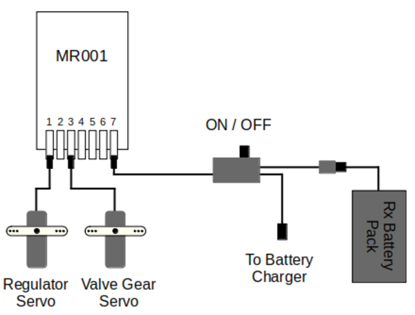
Servo Connection
For live-steam use, MR001c outputs can be connected to standard R/C
servos to operate the regulator, reverser, blower, gas valve and whistle.
MR001c will work with any servo that uses a standard (1ms - 2ms) pulse width
control signal and operates off the selected battery voltage
- e.g. Emax ES08MDII.
The throttle mode should be set to low-off
for separate regulator and direction controls and to ensure that
Emergency Stop (if configured) will
close the regulator.
When used with a Micron model rail transmitter,
throttle is on P1/ch1 controlled using the large speed knob and direction
is on P3/ch3 controlled using the toggle switch (or direction control knob
on Tx24 variants).
The Micron transmitter should ideally be configured for low-off throttle
with no centre detent and a non-biased direction toggle switch.
When used with an aeromodel type stick transmitter, throttle is controlled
using the throttle stick and direction is controlled by the elevator stick.
Servos, plugged into MR001c P1 and P3, are linked to the regulator
and reverser.
The battery can be connected, via an on/off switch,
into any of the unused pins.
Battery Powered Loco
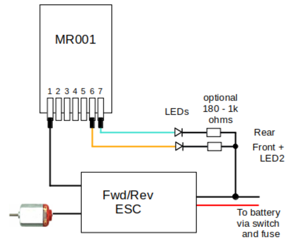
ESC Connection
An Electronic Speed Controller (ESC) that supports forward and reverse
should be connected to P1/ch1 as shown in the diagram.
The MR001c is powered from the ESC 5V output.
The throttle mode
should be set to centre-off or low-to-centre - the latter allows
use of a centre-off ESC while providing separate transmitter
speed and direction controls.
A resettable fuse is essential to protect the battery in the event
of a ESC or wiring fault. The switch must be capable of carrying the
maximum motor current; if a suitable mechanical switch cannot be found,
an electronic switch should be used instead
(contact Micron
for details).
Any of the Micron model rail transmitters can be used or a
Spektrum compatible stick type transmitter.
Tx21v2, Tx22v2
and Tx24v2
transmitters have an inertia control which gives a more realistic
acceleration and deceleration by slowing down the rate at which the
throttle channel is changed.
Binding (top)
MR001c must be bound to a transmitter before use. Once bound, the receiver
remembers the transmitter identity and searches for this when it is
switched on.
To bind a receiver, it is switched on with no transmitter active
(for normal operation, the transmitter should
be switched on before the receiver).
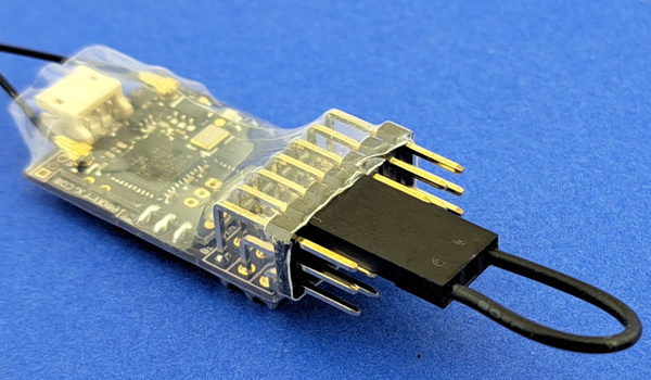
Manual Bind
MR001c enters autobind approximately 5 seconds after switching on if it fails
to find a previously bound transmitter signal.
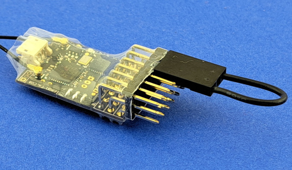
Binding may also be initiated manually by connecting the large
jumper plug across P5 and P7 signal pins (top) row.
Bind mode is indicated by a rapid flashing of the receiver RF LED
and the following steps should be followed to bind with your
transmitter:
- transmitter switched off
- if Selecta
is enabled, move the transmitter loco selection switch to
the required position
- switch on the receiver in bind mode (manual or auto)
- only when the RF LED is flashing rapidly, hold down the
transmitter bind button and switch on
- wait for the transmitter to indicate that it is in bind mode and
then release its bind button (the power LED on Micron model rail
transmitters will flash when binding)
- after a short delay, the RF LED should stop flashing and
go dark and, after another 4-5 seconds, both RF and CPU LEDs will
light and stay on
- the receiver is now bound to the transmitter
If the receiver RF and CPU LEDs do not come on solid (no flash)
within 10-15 seconds, the bind process has failed.
This can happen for several reasons and does not normally indicate a fault.
During binding, the receiver searches for
the transmitter's signal and this can be distorted by holding the transmitter
and receiver too close.
So, if you get a bind fail, try again after moving them slightly further apart
or changing the relative orientation of the aerials.
Binding is most reliable when no other 2.4GHz transmitters are turned on.
Throttle Mode (top)
The MR001c throttle mode determines how transmitter controls
affect receiver outputs, the behaviour of
Directional Lights
and what happens if Emergency Stop is triggered
or Cruise Control is disabled and signal is lost.
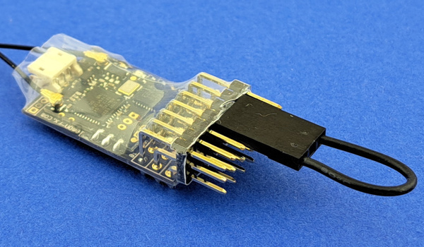
Set Throttle Mode
The throttle mode can be set using a
Power-On Change using the large jumper plug
on pins P3 and P5
or by programming.
The modes are:
- centre-off (1-flash)
-
Forward and reverse on one transmitter control with stop in the centre.
Best used with an external forward/reverse speed controller.
This is the default mode and receivers will be supplied centre-off
unless otherwise requested.
- low-off (2-flash)
- Separate transmitter controls for speed and direction which are
output on separate MR001c ports.
This is the mode used for most live steam locos.
- low-to-centre (3-flash)
- Separate speed and direction transmitter controls are combined
into one forward/reverse output. This mode is intended for battery
electric locos where the user prefers separate controls or who
wants to use a transmitter for both live steam and battery locos.
This mode requires the maximum low and high throttle control positions
to be calibrated. Calibration is forced the first time a receiver
is switched on in this mode. The CPU LED will emit a repeated
flash pattern comprising one long flash followed by 1 or 2 short flashes:
- 1-flash
- move the throttle to the minimum position (stop) and then
move toward full throttle; as the control passes through the
centre position, the flash pattern changes to ...
- 2-flash
- move the throttle to the max position (full throttle) and
then move back toward the centre; as the control passes through
the centre position, the LED will light continously to show
that calibration is complete.
The throttle can be re-calibrated at any time by re-selecting
low-to-centre mode using the large jumper plug or by programming.
In all modes, the throttle output (P1) will not change until the transmitter
control has been set to minimum throttle. This is to prevent the loco
moving immediately the receiver is switched on.
Loco Selection - Selecta (top)
Many Micron model rail transmitters have a 12 way switch to allow control of up to 12 locos - Deltang originated this feature and called it 'Selecta'. Using the switch, locos are brought under control one at a time. When not selected, receiver outputs hold their current setting (e.g. a loco which is moving when deselected keeps moving) and the CPU LED shows a 2-flash pattern. The default 'keep going' behaviour can be changed to stop when deselected by programming the receiver.
The Micron implementation of Loco Selection / Selecta is fully compatible with the Deltang Selecta feature and uses R/C channel 2 by default. When Selecta is enabled, the controlling R/C channel (e.g. 2) may still be mapped to a receiver output but, of course, this will not change as the transmitter switch is rotated.
The receiver has a 800ms delay before enabling when the transmitter Selecta value is changed. This is to avoid obeying the transmitter while the Selecta switch is being moved - e.g. a receiver on Selecta #4 should not change any outputs while the transmitter Selecta switch is moved from #3 to #5.
Selecta may be enabled by default (see the receiver configuration information) and may be enabled or disabled by using a power-on configuration change (see Power-On Configuration Changes) or by programming.
If Selecta is enabled, the transmitter's Selecta switch value will be saved when the transmitter and receiver are bound. A new Selecta value (i.e. switch position) can be stored either by rebinding or by using the power-on changes to disable and then re-enable Selecta.
Note: when the Selecta switch is changed to control a different loco, the newly selected loco responds to the transmitter control settings. The current range of Selecta enabled transmitters have no model memory so cannot have different throttle settings, etc. for each loco. Thus, although Selecta may be used to manage many moving locos, this must be used with care and is not recommended. Micron intends to introduce a transmitter with model memory but the release date is not known.
Directional Lighting (top)
The default configuration has
pins P6 and P7 setup to drive front and rear LED lights;
P6 powers a forward LED and P7 a backward facing LED.
The directional lighting pins can be changed by
programming the receiver.
MR001c has an on-board 3.3V regulator and 220 ohm resistors in series
with the signal pins so limits the LED current to approximately 12mA.
The LED should be connected between the signal and negative pins (top
and bottom rows).
The default setting is for the LEDs to follow the throttle channel with
'centre-off' and is appropriate for a battery loco with ESC.
For live-steam use, the LED behaviour can be reprogrammed for 'low-off' and
this uses full-range throttle on ch1 and directional control on ch3.
To change the way that directional LEDs respond to throttle movement,
set the appropriate throttle mode
using a Power-On Change
or by programming.
Cruise Control (top)
Cruise Control keeps a loco running if a receiver loses the signal
from the transmitter,
for example when going through a tunnel or behind a garden building
or some dense bushes.
All receiver outputs hold their current setting
until the transmitter signal is reaquired.
Outputs also hold when a Selecta-enabled receiver
(see Selecta) is de-selected.
Cruise Control allows you to
switch off the transmitter if, for example, you are running the loco
round a continuous circuit.
The default MR001c setup is Cruise Control enabled.
It can be disabled using a
Power-On Change
or by programming.
If disabled, servos on pins designated as throttle/regulator will be moved
to the stop position when signal is lost.
Emergency Stop (top)
Any of the transmitter controls can be used as an 'Emergency Stop' function
to bring the loco/vehicle to a stop.
Emergency Stop is not enabled by default and must be configured
by programming the receiver.
To enable Emergency Stop, you need to choose:
- the R/C channel
- whether a low or high signal is used to trigger
- the delay before stopping - i.e. the number of seconds that
the R/C channel must be in the trigger state before Emergency
Stop is actioned
For example, the Tx22X transmitter button S2 (in-between the 2 toggle switches)
could be used: this controls R/C channel 4 and the signal is low when
the button is pressed.
Power-On Configuration Changes (top)
A few configuration changes can be made without programming.
A link across the output pins using one or both of the jumper plugs
is used to action the change.
It is best practice to do this with no other connections to the receiver pins.
A change is made by connecting the appropriate P pins with the
receiver off, switching the receiver on and observing the LED flash pattern,
removing the connection which is confirmed by a rapid LED flash
and then switching the receiver off.
Servo end point adjustment and reversing may also be performed using
the small jumper plug to select a servo and then using
the large jumper plug to adjust
- see Servo Throw Adjustment.
The changes all cycle though the flash counts while the jumper is installed.
Each flash count is repeated once (i.e. shown twice)
and then increments to the next,
cycling back to 1 when the maximum is reached.
When the desired flash count has been shown, removing the large jumper
acknowledges the selection by showing a rapid flash. There will be a
short delay between removing the jumper and the rapid flash due to the time
taken to write the changes to permanent memory. The receiver should be powered
off when the rapid flash starts.
If you switch off before removing the jumper connection, the
configuration is not changed. If you switch off after removing the
jumper and before the rapid LED flash, the receiver data is likely to
be corrupted and you should perform a reset.
This is a summary of the configuration changes that can be made,
performed using the large and small jumper plugs. A '-' in the Small Jumper
column indicates that the small jumper is not used.
| Change | Large Jumper | Small Jumper |
LED indication |
|---|
| Reset & Backup |
P1/P3 | - |
n-flash where 'n' is:
1: do nothing
2: reset
3: backup
4: disable/enable ch2/ch4 programming
|
| Configuration Select |
P1/P3 | P4/P5 |
n-flash where 'n' is the configuration number |
| LED2 |
P2/P4 | - |
1-flash - disabled
2-flash = normal, not Select and not Cruise
3-flash = Selecta & Cruise
4-flash= always |
| Throttle Mode |
P3/P5 | - |
1-flash = centre-off (thr=ch1)
2-flash = low-off (thr=ch1, dir=ch3)
3-flash = low-to-centre (thr=ch1, dir=ch3)
|
| Selecta |
P4/P6 | - |
1-flash = disabled
2-flash = enabled |
| Cruise Control |
P4/P6 | P1/P2 |
1-flash = disabled, stop in 4s after signal loss
2-flash = enabled, continue running while no signal |
| Bind |
P5/P7 | - |
rapid flash indicates bind mode |
P1/P3 - Reset & Backup |
P1/P3, P4/P5 - Config Select |
P2/P4 - LED2 |
P3/P5 - Throttle Mode |
P4/P6 - Selecta |
P4/P6, P1/P2 - Cruise |
P5/P7 - Bind |
Receiver Programming (top)
The behaviour for each MR001c pin can be changed
using a bound transmitter.
MR001c must first be put into programming mode and then the
direction toggle switch (knob on Tx24 type transmitters),
or elevator on a stick type transmitter,
is used to enter a program sequence one digit at a time.
The CPU LED (and LED2 if enabled) flashes to indicate the value of
the current step in the programming sequence. For example, if the
current value is 4, the CPU LED flashes 4 times, pauses and repeats -
this is called a 4-flash.
The programming table is large and presented in a separate
document (see micronrc.co.uk/mr001c_progtable) which lists all of
the functions that may be changed by programming.
The table is split into 5 blocks of related functions each with the
same value in the first column.
The programming table columns contain the values which must be
entered to change a particular function.
For example, to change the throttle behaviour
from centre-off (forward and reverse on one control) to low-off
(separate throttle/regulator and direction/reverser controls)
the program sequence 1, 1, 2, 1, 3 is entered. Each digit of this
program sequence is taken from the columns, left to right:
1 = Throttle Configuration
1 = Throttle Number (there is only 1 on MR001c)
2 = Low Off Throttle
1 = Throttle on R/C channel 1
3 = Direction Control on R/C channel 3
One function can be changed at a time. The general method is:
- set receiver into programming mode
- enter a program sequence
- repeat until all programming changes have been made
Enter Programming Mode
There are 2 methods of getting the receiver into programming mode:
- ch2/ch4 method
- Hold the transmitter channel 2 and channel 4 controls at
high or low extremes and then switch the receiver on;
these are the F1 and F2 buttons on a Tx20v2
and the Selecta switch and S2 button on a Tx22X;
the receiver LED will flash rapidly shortly after switch on,
centre one or both channel 2 & 4 controls (e.g. release the buttons
on Tx20v2 or the S2 button on Tx22X).
The MR001c always displays the active configuration immediately
after switch on. This is 2 sequences of 0.5a rapid flash followed
by a number of short flashes equal to the configuration number.
You need to wait for this to complete before looking for the rapid
flash indicating entry to programming mode
- SOS method
- Switch the transmitter and receiver on (they must be bound),
wait 5 seconds without touching any controls and then tap out morse
SOS (... --- ...) on the transmitter bind
button (or toggle the gear switch high to low for a stick transmitter);
- dots (…) will be a quick press of the button and must be
less than 1 second in duration
- dashes (---) must be greater than 1 second and shorter
than 5 seconds – 2 seconds is a reliable time
- the time between each dot or dash must be less than 5 seconds
When programming mode has been successfully entered, the receiver LED
will show a 1-flash - this is the 1 from the first column
of the programming table.
If you do not get the 1-flash, repeat the procedure to enter
programming mode. It can take a couple of
attempts to get the SOS method correct if you have never done it before.
Enter a Program Sequence
One programming change requires up to five choices to be made.
These are called 'levels' and each has several options.
They are documented in the programming table.
Completion of a programming change exits programming mode and requires the
receiver to be placed into programming mode again for the next change.
It is a good idea to write the programming sequence on a piece of scrap
paper and cross off each digit as it is entered so that you
don't lose track of where you are in the sequence.
You always start at the top of the first column and 1-flash is
displayed on entering programming mode.
- The flash count for a level is incremented by setting the
R/C channel 3 control low and back to mid.
- The flash count for a level may be decremented by holding
the R/C channel 4 control low while operating the R/C channel 3
control; R/C channel 4 is available on some Micron transmitters
- e.g. F2 on Tx20v2 and S2 on Tx22X and Tx24v2
- The level value is accepted and the flash count for the next
level is displayed by setting the R/C channel 3 control
high and back to mid.
Most Micron transmitters have a toggle switch on R/C channel 3
which is marked A/B, or forward/reverse for a low-off transmitter:
- pushing the switch down (or toward 'reverse' for a low-off transmitter)
sets the R/C channel to a low value and increments the flash count,
- pushing the switch up (or toward 'forward') sets the
R/C channel to a high value,
accepts the flash count and moves the program sequence
on to next level or exit programming mode if the current level is
the last in the sequence
Always return the toggle switch to centre after pushing down or up.
Refer to the transmitter user manual for specific information
on the R/C channel 3 control - Tx24v2 has a rotary reverser control.
The receiver LED will flash rapidly while R/C channel 3 is high or low and
then return to a slower repeated flash when the control
is back to the middle.
After accepting the flash count for a level, the CPU LED displays
a flash count for the current value of the next level. This could be
higher than 1-flash if the function is set in the receiver configuration
or has been previously programmed. For example:
- the default Selecta R/C channel is 2, so a 2-flash will be
displayed after entering 4, 8, 2
- P6 is configured as a front light, so a 4-flash will be
displayed after entering 3, 6
When the last level for a sequence has been accepted, the CPU LED
will light continously and the receiver is back in normal operating mode.
There may be a short delay between accepting the last sequence value
and the LED lighting continuously - this is is due to the time taken
to write the changes to permanent memory.
The maximum number of levels is 5, but not all sequences use all 5;
if level 5 in the table is blank, the CPU LED will light continously
after level 4 is accepted.
Programming changes are accepted only when the CPU LED lights solid
at the end of the sequence.
If a mistake is made mid way through a sequence,
switch the receiver off to abort.
Programming Example
These examples assume MR001c is in as-received configuration
and a Micron transmitter with toggle switch on R/C channel 3.
Tx24v2 transmitters have a variable control on R/C channel 3 - the Reverser;
the equivalent actions are:
| Action | Tx with toggle switch | Tx24v2 type transmitter |
|---|
| Increment flash count: | toggle down | Reverser fully CCW (reverse) and back to centre |
| Accept flash count: | toggle up | Reverser fully CW (forward) and back to centre |
- Set P2 as normal speed servo on R/C channel 7
program sequence: 2, 2, 1, 7, 1
- enter programming mode
- LED shows 1-flash (level 1, 1=core)
- toggle down and release once,
LED shows 2-flash (level 1, 2=servo)
- toggle up and release,
LED shows 1-flash (level 2, 1=P1)
- toggle down and release 6 times,
LED shows 7-flash (level 2, 7=P7)
- toggle up and release,
LED shows 1-flash (level 3, 1=servo)
- toggle up and release,
LED shows 2-flash (level 4, 2=R/C chan 2 - P2 was prevously a servo on R/C chan 2)
- toggle down and release 5 times,
LED shows 7-flash (level 4, 7=R/C chan 7)
- toggle up and release,
LED shows 1-flash (level 5, 1=normal speed)
- toggle up and release,
LED lights continously and servo on P2 responds to R/C channel 7
- Reverse servo on P3
program sequence: 2, 2, 7, 1
- enter programming mode
- LED shows 1-flash (level 1, 1=core)
- toggle down and release once,
LED shows 2-flash (level 1, 2=servo)
- toggle up and release,
LED shows 1-flash (level 2, 1=P1)
- toggle down and release 2 times,
LED shows 3-flash (level 2, 3=P3)
- toggle up and release,
LED shows 1-flash (level 3, 1=normal servo)
- toggle down and release 6 times
LED shows 7-flash (level 3, 7=adjust servo)
- toggle up and release,
LED shows 1-flash (level 4, 1=reverse servo direction)
- toggle up and release,
LED lights continously and servo on P3 rotates in the opposite direction
- Set P5 as momentary switched output, on when R/C channel 5 is low
program sequence: 3, 5, 1, 5, 1
- enter programming mode
- LED shows 1-flash (level 1, 1=core)
- toggle down and release 2 times,
LED shows 3-flash (level 1, 3=on/off output)
- toggle up and release,
LED shows 1-flash (level 2, 1=P1)
- toggle down and release 4 times,
LED shows 5-flash (level 2, 5=P5)
- toggle up and release,
LED shows 1-flash (level 3, 1=momentary)
- toggle up and release,
LED shows 1-flash (level 4, 1=R/C chan 1)
- toggle down and release 4 times,
LED shows 5-flash (level 4, 5=R/C chan 5)
- toggle up and release,
LED shows 1-flash (level 5, 1=on when chan low)
- toggle up and release,
LED lights continously and a LED on P5 lights when the Tx bind button is pressed
The programming table for MR001c can be found at
micronrc.co.uk/mr001c_progtable.
Servo Throw Adjustment (top)
Servo throws (low and high end points) and reversing can be configured
in 2 ways:
The servo centre position does not change, it will always be at the mid-point
of normal servo rotation.
WARNING: never place the small jumper across
the positive (middle row) and negative (bottom row) pins. This will short
the battery.
The method comprises 2 steps:
- select the servo output to be adjusted using the small jumper
- reverse the servo using the small jumper, or
increase or decrease the servo throw using the large jumper
Only one servo output can be changed at a time, the method must be
repeated for each servo that requires adjustment.`
WARNING: never place the small jumper across
the positive (middle row) and negative (bottom row) pins. This will short
the battery.
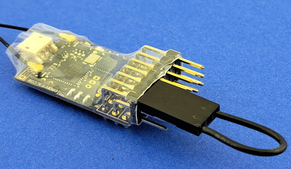
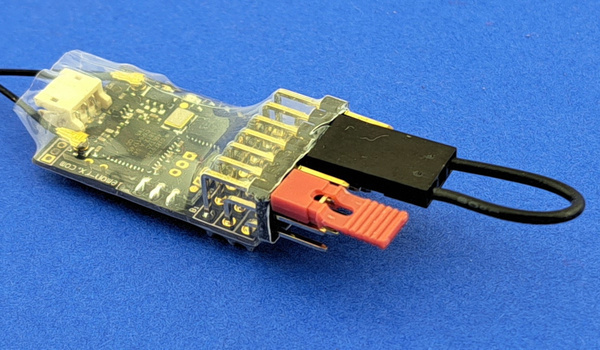
Step 1 - select servo output to adjust
Select P1 to adjust
Servo outputs are on P1 to P5. The small jumper plug is used to select
one of these outputs for adjustment, it is placed across the wanted
signal pin (top row) and the adjacent signal pin.
For example, to select P1 (throttle),
place the small jumper plug across signal pins 1 and 2 as shown in the image
(the black connector in the image is the battery plugged into P4).
Steps:
- receiver must be bound to transmitter
- receiver power off
- transmitter on
- place small jumper on
- P1/P2 to adjust servo output P1
- P2/P3 to adjust servo output P2
- P3/P4 to adjust servo output P3
- P4/P5 to adjust servo output P4
- P5/P6 to adjust servo output P5
- P6/P7 to adjust servo output P6
- P1/P1 and P5/P7 to adjust servo output P7
- plug the battery into a free pin set,
but not P6 or P7
- the CPU LED will flash a sequence twice to indicate the selected pin set
and then flash rapidly - e.g. flash pause flash pause rapid for P1,
flash flash pause flash flash pause rapid for P2, and so on
Note: if the selected pin is not currently configured as a servo
the CPU LED will not flash the pin number sequence and go immediately
to rapid flashing; the receiver will not respond until
it is switched off and back on again
- remove the small jumper plug when the CPU LED is flashing rapidly,
do not remove the battery
- connect a servo, this will respond to the transmitter control
- no other output pin is active
The servo output is now selected. Jumper plugs are used on P6 and P7 to
reverse the servo or adjust the travel end points.
Reversing or end point adjustment can be repeated as often as desired
while the servo is selected. To stop the process, remove power from the
receiver.
Step 2 - adjust selected servo output
The selected servo may now have its direction reversed or have
the travel end points adjusted:
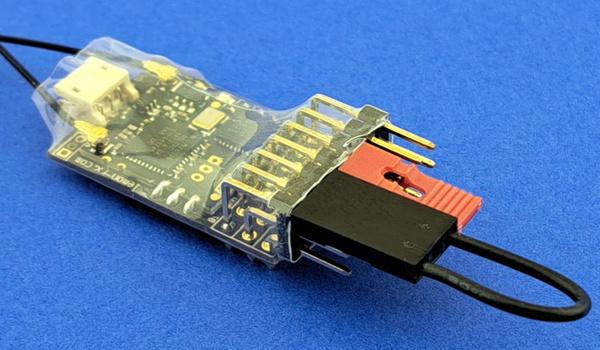
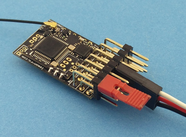
Reverse servo direction
The small jumper plug is placed across signal pins (top row) for P6 and P7
to reverse the servo direction.
The image shows a servo plugged into P1, a battery plugged into P3 and
the small jumper across P6/P7.
Steps:
- select servo output to adjust (see above) and plug servo in
- place the small jumper across signal pins P6 and P7
- the CPU LED will flash rapidly
- remove the jumper
- the CPU LED will stop flashing
- the servo will respond to transmitter controls in the opposite
direction to previous
The servo direction will reverse each time the procedure is executed.
Adjust servo travel
The servo travel end points can be increased or decreased using the large
jumper plug on P6 (decrease) or P7 (increase). The adjustment is done
in small steps every ½ second and the CPU LED flashes for each step.
To make an adjustment:
- move the servo to the low or high end using the transmitter control
- use the large jumper to make changes:
- on P6 to decrease the throw
- on P7 to increase the throw
- either remove the jumper or move the servo away from the end to
stop the adjustment
The CPU LED will stop flashing and the servo will stop moving when the
adjustment limit is reached.
- The limit for decrement is the mid point
of travel so, if an end point is decreased to the maximum amount,
there will be no servo travel in that direction when the transmitter
control is moved.
- The limit for increment is the maximum signal value.
Take care: not all servos will respond to the maximum
range of servo signal values; stop decrementing when the servo
stops moving even though the CPU LED is still flashing.
Reversing or end point adjustment can be performed as many times
as required on the selected servo. When complete, remove power
from the receiver to stop, all changes are stored to the CPU memory.
The next time power is applied, the receiver will operate normally.
Only one servo output can be changed at a time, the method must be
repeated for each servo that requires adjustment.`
WARNING: never place the small jumper across
the positive (middle row) and negative (bottom row) pins. This will short
the battery.
To adjust a servo, the servo output is selected first
and then the travel adjusted using either the throttle control or
direction toggle if the throttle servo is being adjusted.
The steps below assume a Micron transmitter is being used.
If the transmitter is an aeroplane type stick transmitter then
the elevator stick corresponds to the direction toggle.
- put the receiver into programming mode (see above)
- enter the program sequence 2, P, 7, 2, where P is the output
port number (e.g. 3 for P3)
- within 5 seconds, move the control for the output being adjusted to the
end that needs adjustment:
- use the direction toggle or throttle control to increase
or decrease the servo travel:
- use the throttle control if the direction (R/C channel 3) servo
is being adjusted, or
- hold throttle knob fully CCW to decrease travel
- hold throttle knob fully CW to increase travel
- use the direction toggle for all other servos
- hold toggle down to decrease travel
- hold toggle up to increase travel
the receiver LED will flash twice per second as the servo travel is being
adjusted and stop flashing when the limit is reached.
- centre both controls to finish
the adjustment, the receiver will return to normal operating mode
after the control corresponding to the P port being adjusted
has been centred for 5 seconds.
Only one servo output can be changed at a time. Go through the
above steps to adjust a different servo output pin.
Configurations (top)
The pre-loaded configurations are shown below. Unless otherwise
specified when the receiver was ordered, config 1 is enabled by default.
The other loaded configurations can be selected using a
power-on configuration change
or by programming.
P1..P7 are the JR style pins at the front of the receiver,
P8 is the JST-ZH connector at the rear of the receiver and
P9/P10 are on the optional Molex Picoblade connector also at the rear.
Configurations
This configuration table is for version 1.0.
For other versions, refer to mr001c_version.
The pre-loaded configurations are shown below. Unless otherwise
specified when the receiver was ordered, config 1 is enabled by default.
The other loaded configurations can be selected using a
power-on configuration change
or by programming.
| Port |
1: Centre-off throttle, no Selecta |
2: Centre-off throttle, Selecta enabled |
3: low2centre throttle/direction, Selecta enabled |
4: Centre-off throttle, Selecta enabled, sound triggers on P3/P4/P5 |
| H1 |
Centre-Off ch1 |
Centre-Off ch1 |
Low2Ctr ch1, dir ch3 |
Centre-Off ch1 |
| P1 |
Throttle servo or ESC on H1 |
Throttle servo or ESC on H1 |
Throttle servo or ESC on H1 |
Throttle servo or ESC on H1 |
| P2 |
Servo on ch2 |
Servo on ch2 |
Servo on ch2 |
Momentary on ch3, low 0V |
| P3 |
Servo on ch3 |
Servo on ch3 |
Disabled |
Momentary on ch3, high 0V |
| P4 |
Servo on ch4 |
Servo on ch4 |
Servo on ch4 |
Momentary on ch5, low 0V |
| P5 |
Servo on ch5 |
Servo on ch5 |
Servo on ch5 |
Servo on ch5 |
| P6 |
Front Light on H1 (LED2) |
Front Light on H1 (LED2) |
Front Light on H1 (LED2) |
Front Light on H1 (LED2) |
| P7 |
Rear Light on H1 |
Rear Light on H1 |
Rear Light on H1 |
Rear Light on H1 |
| P8 |
Momentary on ch3, low 3.3V |
Momentary on ch3, low 3.3V |
Momentary on ch3, low 3.3V |
Momentary on ch3, low 3.3V |
| P9 |
Momentary on ch3, low 3.3V |
Momentary on ch3, low 3.3V |
Momentary on ch3, low 3.3V |
Momentary on ch3, low 3.3V |
| P10 |
Disabled |
Disabled |
Disabled |
Disabled |
| LED2 |
P6 | P6 | P6 | P6 |
| Selecta |
Disabled |
Enabled |
Enabled |
Enabled |
| Sleep time |
1 hour |
1 hour |
1 hour |
1 hour |
| Cruise |
Enabled |
Enabled |
Enabled |
Enabled |
Other configurations
are available to special order or you can configure yourself
by programming.