Tx20Sv2 is a hand-held wireless transmitter intended to control one
model railway live steam locomotive or a battery electric locomotive
with the ESC set to low-off throttle.
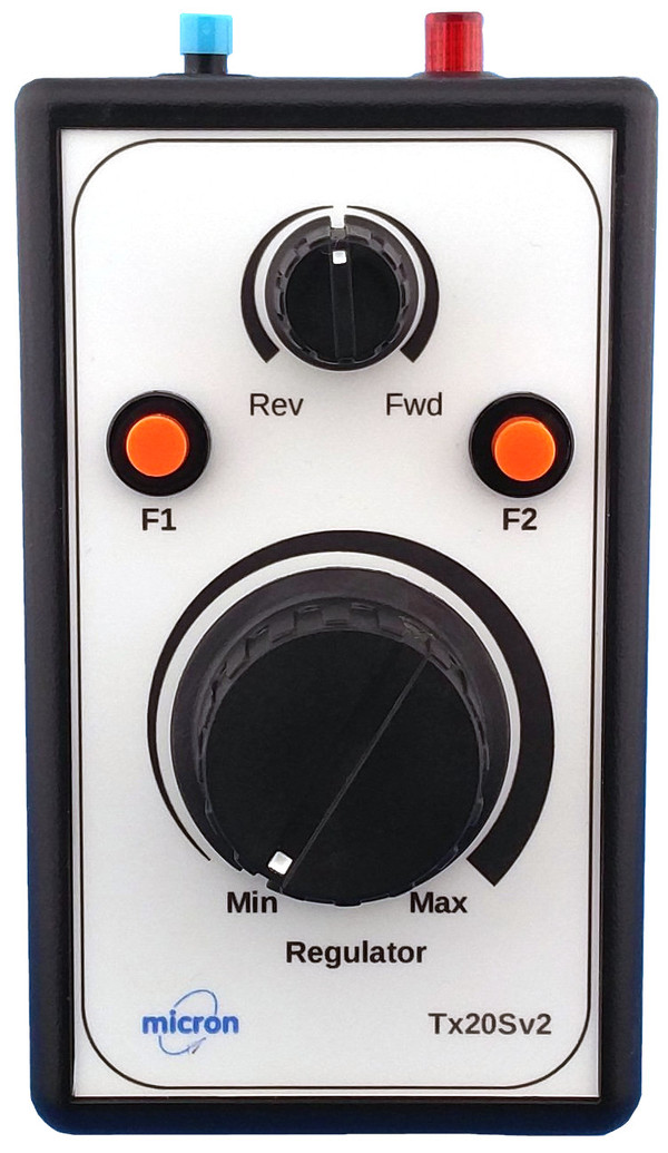
Tx20Sv2 has a large knob for regulator control plus
a smaller knob for valve gear (or ESC direction control) and
three push buttons for auxiliary functions (e.g. a whistle servo).
Tx20Sv2 can be used for Micron and Deltang receiver programming
using the reverser control
to step through programming levels.
Programming details for each receiver may be accessed from the web page
for the receiver.
Technology
- Tx20Sv2 uses the 2.4GHz band which requires no frequency
channel control and is very resilient against interference.
All radio frequency components are contained on the internal
electronics module.
There are no user adjustable parts on this module and it should not
be modified.
- Tx20Sv2 is compatible with all DSM2 receivers; this includes all
Deltang receivers and many Spektrum plus 3rd party Spektrum
compatible receivers.
- Any number of receivers can be bound to your Tx20Sv2 but only one
should normally be switched on at a time to operate them independently.
- Range is suitable for indoors and small outdoor sites; the outdoor
free-air range to a Deltang receiver is at least 50m.
Range indoors is affected by building construction materials,
furniture, people and receiver installation.
- The regulator and direction knob movements and bind push button
action are transmitted as separate R/C 'channels' which must match the
receiver configuration:
| Control |
R/C Channel |
Channel Value |
| regulator knob: | 1 |
| F1 button: | 2 |
button up = mid, button down = low |
| direction knob: | 3 |
| F2 button: | 4 |
button up = mid, button down = low |
| bind/F3 button: | 5 |
button up = high, button down = low |
Battery
The Tx20Sv2 uses a PP3 9V battery, preferably Alkaline or NiMH / Lithium rechargeable.
The maximum working voltage of the internal electronics module is 10V
and there is a protection diode wired in series with the battery lead.
This allows the battery voltage to be up to 10.7V.
If the battery voltage is above this value, the internal
regulator will shut down and the transmitter will not operate.
To replace the battery:
- Make sure that the power on/off button is off (up) before)
adding or removing a battery.
- Remove the lid at the bottom rear of the case by sliding it downwards.
When Tx20Sv2 is new this will require a bit of effort to slide it past the
retaning 'click'. The image at the right shows the case rear with the
battery lid removed.
- Remove the battery from the compartment and pull the battery clip
off the terminals. Replace the clip on the new battery which will only
fit one way round.
TAKE CARE, if force is needed, the connector is probably the wrong way
round.
- Replace the battery cover by sliding it up from the bottom making
sure that the retaining tab goes under the case rear. The battery is
held in place with a piece of foam attached to the cover and you will
feel some resistance as the cover is pushed down onto the battery.
On / Off Switch
Tx20Sv2 has a
2-way latching toggle switch for power and adjacent LED indicator
on the top panel. The power is on when the switch toggle is down - i.e.
pulled toward the front.
The LED lights continuously when the transmitter is on and flashes
when Tx20Sv2 is in bind mode (see below).
It is best to switch the transmitter on before the receiver.
If a receiver is switched on with Tx20Sv2 off, it is likely
to enter bind mode with rapid flashing of the LED on the
receiver board. If you did not intend to bind, switch the
receiver off, then switch Tx20Sv2 on followed by the receiver.
Regulator Knob
The regulator control is low-off with no centre-click and operates
R/C channel 1.
Off/Stop is at the fully counter-clockwise rotation (left/CCW) of the knob and
speed increases at the knob is rotated clockwise (right/CW).
Direction Knob
The direction control has a centre-click and operates R/C channel 3.
It is typically used to control a servo connected to the loco reversing gear.
If used with a receiver that has built-in ESC, the receiver must be
configured for 'low off', full-range motor control.
F1 & F2 Push Buttons
The two auxiliary function push buttons F1 and F2 may be used to
control lighting, couplers, sound cards, etc.
All model rail receivers available from Micron can be configured with
momentary (press for on, release for off) or latching (press for on,
press again for off) outputs that may be operated by F1 or F2.
Bind Button
If a receiver has not previously been bound, it has to be 'paired' with the transmitter. Binding is only required once per receiver.
- Put your receiver into Bind mode (if a Micron or Deltang receiver, switch it on and wait for the LED to flash fast).
- Press and hold the Bind push-button on the transmitter.
- Switch the transmitter on by pushing the Power button and then release the Bind button.
- Binding is complete when the receiver LED stops flashing.
During normal operation, the bind button can be used as an auxilary control - e.g. horn or whistle sound trigger.
TAKE CARE to avoid holding the bind button down for 20 seconds or more as this will cause the transmitter to enter calibration mode or reconfigure some of the controls.
Receiver Programming
You need to refer to the receiver's programming instructions for details of
the available functions and the programming sequence to modify the functions.
The universal method of putting Micron and Deltang receivers into
programming mode
requires R/C channels 2 and 4 - buttons F1 and F2.
The alternative method is to tap out Morse ‘SOS’ on the Bind/F3 button.
To Enter Programming Mode using F1 and F2:
- Centre the direction knob
- Switch the Tx on and hold down both F1 and F2
- Apply power to the Rx and its LED will start rapid flashing
- Release F1 and F2
The Rx LED will now show a 1-flash – this is a repeated single short
flash followed by a longer pause. This first flash pattern
is called the 'Menu' in the programming instructions.
To Enter Programming Mode using the SOS method:
- Centre the direction knob
- Switch the Tx and Rx on and wait for the Rx LED to stay on solid;
you should now have normal control of the model
- Wait at least 5 seconds without touching any controls
- Tap out the morse code ‘SOS’ on the bind button (… --- …)
- dots (…) will be a quick press of the button and must be
less than 0.7 seconds in duration
- dashes (---) must be greater than 0.7 seconds and shorter
than 5 seconds – 2 seconds is a reliable time
- the time between each dot or dash must be less than 5 seconds
- If the SOS pattern is recognised, the Rx LED will display a
repeating single-flash (1-flash pause and repeat)
- If you do not get the 1-flash, go back to step 3 and repeat the SOS
- Switch the Rx off at any time to abort
To make changes to receiver settings:
One programming change requires up to five choices to be made.
These are called 'levels' and each has several options.
They are documented in the programming table for the particular receiver;
the Micron web page description for a receiver contains a link to
the programming table for that receiver.
Completion of a programming change exits programming mode and requires
the F1/F2 or SOS method to be entered again for the next change.
You have to remember which level you are changing and the repeating
LED flashes display the current option for that level.
It is a good idea to write the programming sequence on a piece of scrap paper
and cross off each digit as it is entered.
You always start at level 1.
For example, the first choice is the Menu number (programming group).
The first option (1-flash) is for changing 'H' (ESC) outputs,
the second (2-flash) is Menu 2 to change P outputs for servos,
3-flash is for Menu 3 to change P outputs for on/off switching, etc.
Refer to the Programming Table for your receiver to find the number of
options and what they change.
Each level is in a separate column, 1 to 5 left to right.
For example, to configure a Deltang Rx6 receiver output P4 to switch on (3.3V)
when F1 is pressed (R/C channel 2 is low),
the programming sequence is 3,4,1,2,1,
where:
3 = Menu 3
4 = P4
1 = momentary on/off
2 = R/C channel 2
3 = output idle 0V, 3.3V when channel is high (F1 pressed)
The general procedure for entering a programming sequence is, for each level:
- rotate the direction knob Rev/CCW and back to centre to increment
the Rx LED flash count (called NO choices in the Deltang documentation);
repeat this until the Rx LED is showing the correct flash count for
the programming level
- rotate the direction knob Fwd/CW and back to centre to accept the
current flash count for the current level (called a YES choice in
Deltang documentation) and move on to the next level in
the programming sequence
When you make a choice with the direction knob (Fwd or Rev),
the Rx LED will briefly flash rapidly and then the LED will:
- direction knob Fwd/CW:
display the current flash count for the next programming level or
light solid when the end of the programming sequence is reached
- direction knob Rev/CCW:
display the next flash count for the current level;
each programming level has a maximum flash count after which the flash
count returns to 1 with another Rev/CCW movement of the direction knob
Changes are saved automatically when the Rx LED lights solid at the end
of a programming sequence. If a mistake is made mid way
through a sequence, switch the Rx off to abort.
Repeat the above steps for each program function that you wish to alter.
For example, to set the ESC output (the first if the receiver has multiple ESC) to respond to full range regulator on channel 1 and
direction control on channel 3, the programme sequence is 1,1,2,1,3:
- Enter programming mode
- Rx LED displays 1-flash, direction knob Fwd/CW to accept
- Rx LED displays 1-flash, direction knob Fwd/CW to accept
- If rx LED does not display 2-flash, rotate direction knob
Rev/CCW until it does,
then direction knob Fwd/CW to accept
- If Rx LED does not display 1-flash,
rotate direction knob Rev/CCW until it does,
then direction knob Fwd/CW to accept
- If Rx LED does not display 3-flash,
rotate direction knob Rev/CCW until it does,
then direction knob Fwd/CW to accept
- Rx LED lights solid
Calibration
All ready-to-use transmitters are calibrated as the final manufacturing step.
This normally only needs to be done once.
If you suspect that the regulator control is not operating correctly or
you have replaced any of the internal components (e.g. regulator potentiometer),
your transmitter may need calibration.
If the bind button has been inadvertently held down for longer than 20 seconds,
the previously stored calibration data will have been overwritten and
you could find that the regulator control behaves strangely.
To perform calibration:
- Centre the regulator knob (white mark pointing toward
the top of the Tx)
- Centre the direction knob
- Switch the Tx on
- Within 60 seconds, press and hold the bind button
- After 20 seconds, the Tx LED will go off
- Release the bind button, the Tx LED come back on
The Tx is now calibrated.