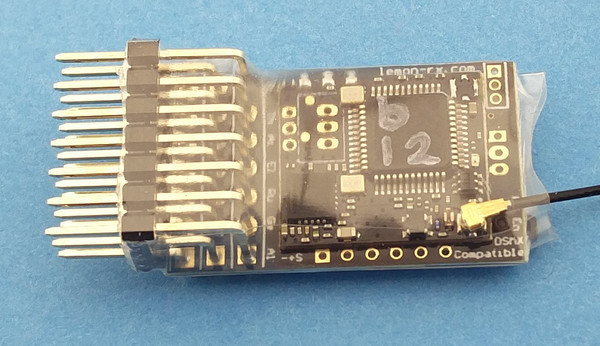
MR001b Bottom
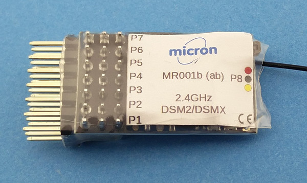
MR001b Top
The MR001b receiver is well suited for use
in large scale live-steam or
battery powered locos. It operates on 2.4GHz using the Spektrum DSM2 or DSMX
protocols; thus it works just like any other DSM2/DSMX receiver but
includes some useful features for model railway control.
The MR001b is small (30x18x11mm) and space for it is easily
found in most locos.
The MR001 family of receivers includes two hardware variants:
- single extended aerial and manual bind (requires jumper plug for bind)
- two extended aerials for diversity reception (the receiver takes data from the aerial with the strongest signal) and auto bind (receiver goes into bind mode 5 seconds after failing to find a transmitter signal)
and two firmware variants:
| MR001a: | - all outputs configurable as servo, momentary switched or latching switched
- LED2 status can be assigned to any output
- all setup done from transmitter, including servo reversing and travel adjustment
|
| MR001b: | - output configuration fixed at servo on 1-5, forward and reverse lights on 6&7 LED2 on pin 6
- servo reversing and travel adjustment using jumpers on output pins
- no programming from transmitter
|
The MR001b free-air range, when used with a Micron low-power transmitter,
is 40m-50m and approximately 200m when used with
a full-power (100mW) transmitter.
This range will be reduced indoors due to absorption by furniture / fittings
and reflections from metal surfaces.
Range is also reduced if the receiver aerial is in a metal enclosure.
Ideally, the aerial should be placed outside the vehicle body and clear of
any metal.
The 30mm active tip of the extended aerial needs to 'see' the transmitter so
should be placed through a hole in the loco body - e.g. into the cab space.
The MR001b aerial should not be cut short or made longer as this will
affect operation of the receiver.
It is important to perform a range check after installation to ensure
you have full control of your loco at all positions around the layout.
Features (top)
- Compatible with all DSM2 and DSMX transmitters with up
to 10 R/C channels, both Micron
model rail and aero model stick type transmitters.
- 3.45V to 8.4V working voltage range.
- 8 outputs which are configured for 5 servo, 2 auto-switched front/rear
LED lights and 1 x low-current switched.
- All outputs have a 220 ohm series resistor which allows
direct connection of a low-current LED.
- Supports the Deltang Selecta feature
for compatibility with multi-loco transmitters, MR001b must
be manually bound to change Selecta switch position.
- Auto-switched front and rear lights, configurable for centre-off
or low-off throttle on channel 1 (output P1).
- Servo outputs reversible and adjustable end-points.
- Outputs maintain previous setting on signal loss.
- Receiver CPU LED repeated to P6 which is the front LED light.
Connections and Indicators
MR001b has 7 sets of output pins which can be used for servos or LEDs
for lighting.
The pin sets, numbered from the top of the diagram below, are 0.1"
pitch to take standard R/C plugs.
An additional 8th output for LED or sound card trigger is available via
a JST-ZH socket at the rear of the receiver - this output
cannot be used for connecting a servo as the positive pin is powered
from the on-board 3.3V regulator which has insufficient current
capacity for a servo.
MR001b can be powered from a battery of 3.45V up to 8V;
use of a 4 or 5 cell NiMH rechargeable battery or
the 5V regulated output from a speed controller is typical.
The standard configuration has servo outputs on P1 to P5,
front/rear lighting on P6 and P7 and a channel 3 switched output
on P8:
| P1: | servo on ch1, throttle |
| P2: | servo on ch2, F1 on Tx20, optional servo on ch7 for Selecta transmitters |
| P3: | servo on ch3, toggle switch on Micron tx |
| P4: | servo on ch4, F2 on Tx20 |
| P5: | servo on ch5, bind button on Micron tx |
| P6: | front LED & LED2 |
| P7: | rear LED |
| P8: | idle 0V, 3.3V when ch3 is low (Micron tx toggle down) |
Other configurations can be supplied to special order at no
additional cost.
MR001b has 2 LED indicators, one on the top near the aerials and another
on the bottom, these are labeled 'LED RF' and 'LED CPU' on the diagram below.
There are actually
2 LEDs on the bottom, but only one of them is used.
- RF LED:
- indicates when a good signal is received,
flashes rapidly when the rx is in bind mode and
flashes slowly if the receiver power was interrupted
- CPU LED:
- indicates the receiver status:
- flashes slowly after switch on an waiting for a good
transmitter signal
- lights continously when a good R/C signal is being decoded
- flashes twice, pause and repeat when the receiver
is deselected (see Loco Selection)
- used for feedback when setting servo travel end points
or reversing servo direction
Live Steam
For live-steam use, the MR001b outputs can be connected to standard R/C
servos to operate the regulator, reverser, blower, gas valve and whistle.
MR001b will work with any servo that uses a standard (1ms - 2ms) pulse width
control signal and operates off the selected battery voltage
- e.g. Blue Arrow 3gm.
When used with a Micron model rail transmitter,
throttle is on P1/ch1 controlled using the large speed knob and direction
is on P3/ch3 controlled using the toggle switch.
The Micron transmitter should ideally be configured for low-off throttle
with no centre detent and a non-biased direction toggle switch.
When used with an aeromodel type stick transmitter, throttle is controlled
using the throttle stick and direction is controlled by the elevator stick.
Servos, plugged into MR001b P1 and P3, are linked to the regulator
and reverser.
The battery can be connected, via an on/off switch, into any of the unused pins.
Battery Powered Loco
An Electronic Speed Controller (ESC) that supports forward and reverse
should be connected to P1/ch1 as shown in the diagram.
The MR001b is powered from the ESC 5V output.
The resettable fuse is essential to protect the battery in the event
of a ESC or wiring fault. The switch must be capable of carrying the
maximum motor current; if a suitable mechanical switch cannot be found,
an electronic switch should be used instead
(contact Micron
for details).
Any of the Micron model rail transmitters can be used or a
Spektrum compatible stick type transmitter.
Tx21 and Tx22
transmitters have an inertia control which gives a more realistic
acceleration and deceleration by slowing down the rate at which the
throttle channel is changed.
Binding (top)
MR001b must be bound to a transmitter before use. Once bound, MR001b
remembers the transmitter identity and searches for this when it is
switched on.
When binding, we recommend that servo rods are disconnected in
case they are incorrectly set.
Battery powered locos should have the motor unplugged in case
the throttle is not set correctly or the ESC not calibrated for the
throttle off position.
To bind a receiver, it is switched on with no transmitter active
(for normal operation, the transmitter should
be switched on before the receiver).
Manual Bind
Some variants of MR001b support autobind where the receiver automatically
goes into bind mode approx 5 seconds after switching on with no pre-bound
transmitter active. If autobind is available, this will be indicated
on the receiver label. All variants support manual binding.
- manual bind:
- The large jumper plug supplied with the receiver is connected
across the signal pins (top row) for P5 and P7 and then the
receiver is switched on. If fitted, P5 servo and P6/P7 LEDs must be
removed when manual binding.
- auto bind:
- The receiver enters bind mode approximately 5 seconds after power-on
if it has either never been bound or it fails to find its
bound transmitter. It is not necessary to remove the
plugs for P5 servo or P6/P7 LEDs when using auto-bind.
Bind mode is indicated by a rapid flashing of the receiver RF LED
and the following steps should be followed to bind with your
transmitter:
- transmitter switched off
- if Loco Selection
is enabled, move the transmitter loco selection switch to
the required position
- switch on the receiver in bind mode (manual or auto)
- only when the RF LED is flashing rapidly, hold down the
transmitter bind button and switch on
- wait for the transmitter to indicate that it is in bind mode and
then release its bind button (the power LED on Micron model rail
transmitters will flash when binding)
- after a short delay, the RF LED should stop flashing and
go dark and, after another 4-5 seconds, both RF and CPU LEDs will
light and stay on
- the receiver is now bound to the transmitter
If the receiver RF and CPU LEDs do not come on solid (no flash) within 10-15 seconds,
the bind process has failed. This can happen for several reasons and does
not normally indicate a fault.
During binding, the receiver searches for
the transmitter's signal and this can be distorted by holding the transmitter
and receiver to close.
So, if you get a bind fail, try again after moving them slightly further apart
or changing the relative orientation of the aerials.
Binding is most reliable when no other 2.4GHz transmitters are turned on.
Loco Selection (top)
Tx22, Tx24
and Tx72
have a 12 way switch to allow control of up to 12 locos.
Using the switch, locos are brought under control one at a time.
When not selected, MR001b outputs hold their current setting (e.g. a
loco which is moving when deselected keeps moving)
and the CPU LED shows a 2-flash pattern.
The implementation of Loco Selection in MR001b is fully compatible
with the Deltang Selecta feature and uses R/C channel 2 by default.
When Loco Selection is enabled, the controlling R/C channel (e.g. 2)
may still be mapped to a servo output but, of course, this will not change
as the transmitter switch is rotated.
The receiver has a 800ms delay when the transmitter Selecta value is changed.
This is to avoid obeying the transmitter while the Selecta switch
is being moved - e.g. a receiver on Selecta #4 should not change any outputs
while the transmitter Selecta switch is moved from #3 to #5.
Loco Selection Toggle
MR001b is normally supplied with Loco Selection disabled.
To toggle whether Loco Selection is enabled or disabled:
- turn off the receiver and transmitter
- put the large jumper plug on signal pins (top row) for P4 and P6
- switch the receiver ON and the CPU LED will display
- 1-flash if Loco Selection is disabled
- 2-flash if Loco Selection is enabled
- remove the plug and the CPU LED will display a rapid flash
until the receiver is switched off
If Loco Selection was enabled, the transmitter's switch value
will be saved the next time the transmitter and receiver are switched on.
A new selection value can be stored either by performing the above steps
again or by binding.
Directional Lighting (top)
Pins P6 and P7 can be used to drive front and rear LED lights;
P6 powers a forward LED and P7 a backward facing LED.
The directional lighting pins can be changed by
programming the receiver.
MR001b has an on-board 3.3V regulator and 220 ohm resistors in series
with the signal pins so limits the LED current to approximately 12mA.
The LED should be connected between the signal and negative pins (top
and bottom rows).
The default setting is for the LEDs to follow the throttle channel with
'centre-off' and is appropriate for a battery loco with ESC.
For live-steam use, the LED behaviour can be reprogrammed for 'low-off' and
this uses full-range throttle on ch1 and directional control on ch3.

Set Throttle Type
To toggle whether the directional LEDs operate as 'centre-off' or 'low-off':
- turn off the receiver and transmitter
- put the large jumper plug across signal pins (top row) P3 and P5
- switch the receiver ON and the CPU LED will display:
- 1-flash for low-off
- 2-flash for centre-off
- remove the plug and the CPU LED will display a rapid flash
until the receiver is switched off
Reset (top)
The receiver settings can be reset back to the as-supplied configuration
using the large jumper across signal pins P1 and P3. This removes any
servo adjustment changes that have been made.
To reset:
- turn off the receiver
- put the large jumper plug across signal pins (top row) P1 and P3
- the CPU LED will flash once per second
- remove the jumper plug
- the receiver will reset and the CPU LED will flash rapidly
until the receiver is switched off
Jumper Changes (top)
This is a summary of the configuration changes that can be made using
a large jumper across the signal pins:
| Manual bind | P5 & P7 |
| Loco Selection (Selecta) toggle | P4 & P6 |
| Throttle centre-off/low-off toggle | P3 & P5 |
| Reset to factory setup | P1 & P3 |
Other jumper settings are used to change servo direction and alter
the servo travel end points (see below).
Servo Adjustment (top)
Servo direction and throws (low and high end points) can be changed
using the supplied small and large (bind) jumper plugs.
The method is simple and comprises 2 steps:
- select the servo output to be adjusted using the small jumper
- reverse the servo using the small jumper, or
increase or decrease the servo throw using the large jumper
Reversing or end point adjustment can be performed as many times
as required on the selected servo. When complete, remove power
from the receiver to stop, all changes are stored to the CPU memory.
The next time power is applied, the receiver will operate normally.
Only one servo output can be changed at a time, the method must be
repeated for each servo that requires adjustment.`
WARNING: never place the small jumper across
the positive (middle row) and negative (bottom row) pins. This will short
the battery.
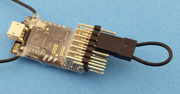
Step 1 - select servo output to adjust
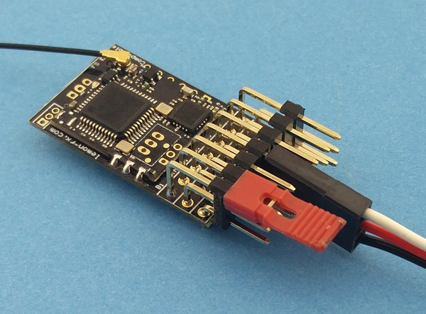
Select P1 to adjust
Servo outputs are on P1 to P5. The small jumper plug is used to select
one of these outputs for adjustment, it is placed across the wanted
signal pin (top row) and the adjacent signal pin.
For example, to select P1 (throttle),
place the small jumper plug across signal pins 1 and 2 as shown in the image
(the black connector in the image is the battery plugged into P4).
Steps:
- receiver must be bound to transmitter
- receiver power off
- transmitter on
- place small jumper on
- P1/P2 to adjust servo output P1
- P2/P3 to adjust servo output P2
- P3/P4 to adjust servo output P3
- P4/P5 to adjust servo output P4
- P5/P6 to adjust servo output P5
- plug the battery into a free pin set,
but not P6 or P7
- the CPU LED will flash a sequence twice to indicate the selected pin set
and then flash rapidly - e.g. flash pause flash pause rapid for P1,
flash flash pause flash flash pause rapid for P2, and so on
- remove the small jumper plug when the CPU LED is flashing rapidly,
do not remove the battery
- connect a servo, this will respond to the transmitter control
- no other output pin is active
The servo output is now selected. Jumper plugs are used on P6 and P7 to
reverse the servo or adjust the travel end points.
Reversing or end point adjustment can be repeated as often as desired
while the servo is selected. To stop the process, remove power from the
receiver.
Step 2 - adjust selected servo output
The selected servo may now have its direction reversed or have
the travel end points adjusted:
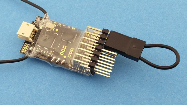
Reverse servo direction
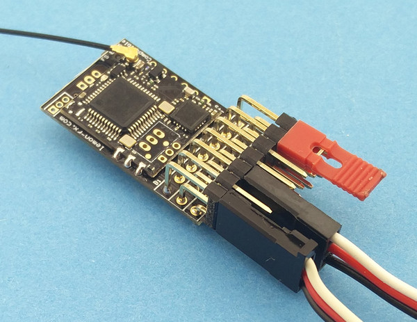
Reverse direction of P1 servo
The small jumper plug is placed across signal pins (top row) for P6 and P7
to reverse the servo direction.
The image shows a servo plugged into P1, a battery plugged into P3 and
the small jumper across P6/P7.
Steps:
- select servo output to adjust (see above) and plug servo in
- place the small jumper across signal pins P6 and P7
- the CPU LED will flash rapidly
- remove the jumper
- the CPU LED will stop flashing
- the servo will respond to transmitter controls in the opposite
direction to previous
The servo direction will reverse each time the procedure is executed.
Adjust servo travel
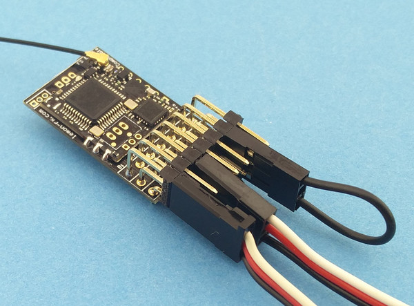
Decrease throw
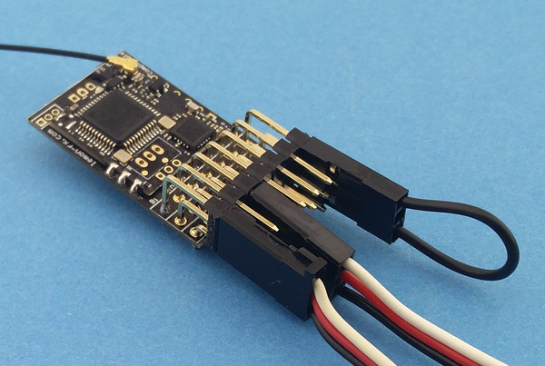
Increase throw
The servo travel end points can be increased or decreased using the large
jumper plug on P6 (decrease) or P7 (increase). The adjustment is done
in small steps every ½ second and the CPU LED flashes for each step.
To make an adjustment:
- move the servo to the low or high end using the transmitter control
- use the large jumper to make changes:
- on P6 to decrease the throw
- on P7 to increase the throw
- either remove the jumper or move the servo away from the end to
stop the adjustment
The CPU LED will stop flashing and the servo will stop moving when the
adjustment limit is reached.
- The limit for decrement is the mid point
of travel so, if an end point is decreased to the maximum amount,
there will be no servo travel in that direction when the transmitter
control is moved.
- The limit for increment is the maximum signal value.
Take care: not all servos will respond to the maximum
range of servo signal values; stop decrementing when the servo
stops moving even though the CPU LED is still flashing.